
beginning
For this project my partner and I were required to design and simulate a copy jam detector. We had to use sensors, motors, and resistors, however with a shortage of supplies and not enough mutual understanding, we did not have to complete this project on the breadboard. My circuit had to monitor three sensors (A,B,C) and it had to stop the copier when a paper jam was detected by using LEDs.

|

|
Part explanation
Resistors- Did not use any however they are used in this circuit to limit the amount of voltage that goes into the lights through the circuit.
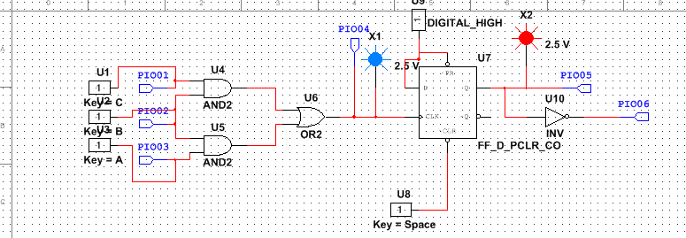
Combinational Logic Circuit- Used to detect when one of the sensors jams. The system is wired so that when the light sensors of adjacent sensors (AB / BC) no longer detect the light source the signal of a jam goes through the circuit and stops the motor, starts the buzzer and turns on the LED
Flip-Flop- Used to make sure than the buzzer stays on even when the jam is cleared while the LED turns off as soon as the jam is cleared
LED vs. Buzzer- The LED lights up at the same time the buzzer starts to go off. The LED turns off as soon as the jam is no longer present. The buzzer stays on however to allow the user to investigate the jam and check/fix the machine before resetting the buzzer. This allows a double check of the machine before the motor turns on again and allows more paper to pass through.
conclusion
Previous projects have implemented switches and buttons when this project used motors, even though we didn't get to use them. It seemed to me that this PLD design was much easier to construct than previous projects. During this project I really learned the difference between synchronous and asynchronous counters.
