truth table

I needed to fill out this truth table to figure out what switches needed to be on to display different combinations. I also used this truth table to figure out the logic expressions that I needed to know how to wire my circuit.
k-maps
I created these K-maps in order to simplify my truth table without using Boolean algebra. K-Mapping is a less tedious way to simplify, and creates less room for error. To K-Map, you need to group the biggest rectangle of 1's possible, while still using all of the 1's, and figure out what variable(s) stays the same. As you can see I have some boxes that contain an X. X's can mean either 1 or 0, depending on if it can help you to make a bigger rectangle or not. I have columns labeled A-G because those are the seven segments on the common cathode display. Each line you see is a different segment on the display.

Multisim implementation

For my Multisim implementation, I used the Bus function in order to condense the wires and make it easier to troubleshoot. The Bus function allows you to connect wires to the Bus and while you tell it what connection you want it to have. In Multisim I used 6 gates, however I do not need 6 chips, I only need 4. These are only 2-input gates, when the chips can have up to 4 inputs. Since I have a somewhat easy birthday to display, NAND and NOR implements didn't have that much of an effect. I only used the NAND because I had to. We use these implements because they are more efficient and can save money. You use logic expressions to tell the seven segment display what to display. Every segment has a different display. For example my A segment is notZ+notY, that is how my A segment turned on. If we used common anode, we would have to run all of our final equations through an inverter, because common anodes look for zeros while common cathodes look for ones, that's why a common cathode was ideal for this project.

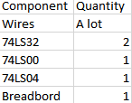
bill of materials |
|
On my breadboard, I used 2 74LS32 (AND) chips, 1 74LS00 (NAND) chip, and 1 74LS04 (inverter) chip, and a bunch of wires.
Breadboarding

|

|
This is my final breadboard, displaying the 5 and the 4 for May 4th. This was my second breadboarding experience so I was still a little rusty on knowing all the functions of the different chips. I made the mistake of loading up all the wires on the same three input-output columns on the AND chip, however I fixed this and it turned out i needed another AND chip. If I had followed directions and color coded the segments it would have been much easier to troubleshoot.
conclusion
From this project, I learned that I should follow directions more clearly and that wiring actually isn't that bad. If I had the chance to do this again I would definitely color code the segments, but hopefully I wouldn't need to troubleshoot. K-Mapping is very useful because I didn't fully get the concepts of Boolean algebra but I don't even have to worry about that when I K-Map. Overall this project was a good learning process and helped me underrtsand wiring and NOR and NAND gates a lot better.
