
overview
The purpose of this project was to use all of our knowledge we have learned over the past couple weeks, put it together, and create a counter such as the one we see at the DMV that counts from 0-80 and pauses at 80. It also needs a switch that resets it to 0.
multisim circuit

pld circuit

When creating a design in PLD mode, you are replicating the design of the actual circuit you are about to make. You need to upload your PLD design to a breadboard and wire it accordingly to your pins and buttons on your design. Using PLD mode saves you a lot of time because you only need a little bit of wires in contrast to design mode when you have to use an ungodly amount of wires, and if you mess up, troubleshooting is like trying to find a needle in a haystack.
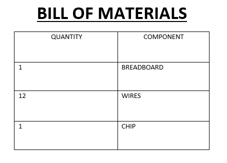
These are the necessary amounts of materials that I used to construct my design.
conclusion
Although frustrated due to lack of time and missing school, I did learn a lot from this project. This project really helped me decipher the difference between synchronous and asynchronous counters and what their functions are. An asynchronous counter controlled my ones display, and using a couple NAND gates, I designed it so every time when it detected a 10, it would link over to the other display and display a 1,2,3.... My tens display was also controlled by an asynchronous counter, and I designed it so when it reached an 8, it would pause there and not do anything until the reset button was pressed.
